
Lighting LED with AC main supply were not that easy. Mainly it required some sort of SMPS with current controlling circuitry. But it is changing. Now there are integrated circuits available specially designed to help to light LEDs with few extra components. One of such IC is CYT1000B.
I like CYT1000B more compared similar ICs in its category because it requires fewer components.
What I most dislike about CYT1000B is that it can only be used drive up to 60mA, thus cannot be used to light most of power LED chips. However, 3528 LEDs are rated 60mA so can be used.
Caution: The circuit I am discussing in this post is connected directly to main AC supply without any isolation. Never touch any of the component while it is in operation. Always make sure you are disconnected from main supply before touching the components or PCB.
Here is a schematic to build an LED light.
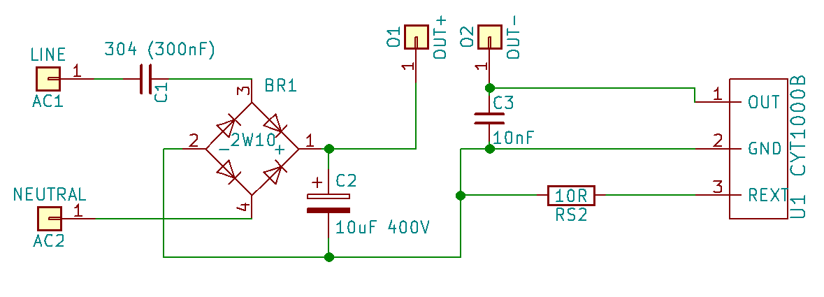
This circuit is to provide 60mA output current. Theoretically we can use as many as LEDs that its series voltage is within supply voltage. So, theoretically we can use up to 60 pieces 3528 LEDs in series with above circuit, but I don’t think that will work practically.
We need to provide enough copper padding for CYT1000B which is in TO252-2 package.
So listed components are:
- CYT1000B
- 304 (300nF) Polyethylene film capacitor rated 400V or above.
- Bridge rectifier — Four diodes or 2W10 or DB207
- 10uF / 400V electrolytic capacitor
- 10nF ceramic capacitor
- Resistor — In above schematic I used 10R which is to provide current of 60mA. Please read below to see how to calculate this resistor value.
- One or more LEDs in series connected to OUT- and OUT+ terminals.
We can use AC supply up to 250V. The capacitor C1 is to limit current from main supply. Regarding C3, I was not sure about the type ceramic of capacitor to be used, but both multi-layer ceramic and high voltage ceramic capacitors worked for me. But I think high voltage ceramic capacitor would be more safe to use.
Controlling Output Current
The RS2 resistor is being used to control the output current and it needs to be calculated. As per CYT1000B datasheet, output current calculation formula is 600mV / Rs.
So, using 10R resistor, output current will be 60mA.
As per the datasheet, 60mA is the maximum allowed output current, thus 10R appears to be the minimum resistor value we can use in this application. Increasing resistance will decrease the output current.
Leave a Reply