OP07 based thermocouple signal amplifier

Thermocouple Amplifier with OP07C Op-Amp

Recently I created a soldering station based on Arduino Pro mini. It has to read temperature data from a thermocouple within the soldering iron. Thermocouple produces a very little voltage, around up to 30 Milli volts for soldering irons. So, the soldering station uses an op-amp based circuit to amplify those small signals from the thermocouple to a signal high enough for the microcontroller’s ADC channel can detect. I noticed many DIY makers on Internet use LM358 as the op-amp for those amplifier circuits, while researching on the topic. I learned LM358 is not a good choice for the purpose because it has relatively high off-set voltage, a voltage op-amp gives in output when input voltage is 0. Then I researched many many designs and finally settled to use OP07C op-amp IC.

OP07 is labeled as instrumentation precision operational amplifiers. It is specially designed for instrumentation amplifiers that involve in reading very small signals.

Before OP07C, I decided to use INA128, I ordered pack of 5 from AliExpress though its price was bit high. Fortunately, the supplier did not deliver it saying it went out of stock and price will be even higher for the new stock. That was lowest price listed I could found for INA128! So, I canceled the order and continued my search for alternatives. Finally settled with OP07C, which happened to be much cheaper than INA128.

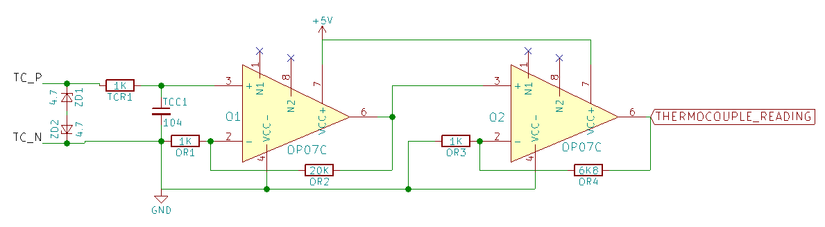
Later, after learning more about basic op-amp circuits and its designing. I designed a circuit to help reading signal from the thermocouple. Before putting further details of it, here is its schematic with component values.

OP07 based thermocouple signal amplifier
OP07 based thermocouple signal amplifier (Click to view larger).

Components

As you see, following are components required for this circuit:

  • OP07C op-amp — 2 nos.
  • 1KΩ resistors — 3 nos.
  • 20KΩ resistor — 1 no.
  • 6K8Ω (6.8KΩ) resistor — 1no.
  • 4.7 V Zener diode — 2 nos.
  • 100nF (104) ceramic capacitor — 1no.

Gain Calculation

As I already mentioned, thermocouples produce very small voltage signals when heated up. A K-type thermocouple produces 24.905 Milli volts when its temperature is at 600°C.

Assuming our soldering iron may heated up to 600°C and its signal can be amplified up to 4.2V. We need an amplifier circuit with gain of 4.2 / 0.024905 = 168.64

We can set gain of an op-amp by choosing appropriate resistors values. Here is a non-inverting op-amp circuit model, which I used in above schematic.

Non-inverting op-amp circuit

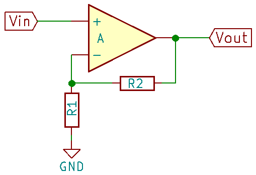
The gain of this circuit will be (R2 / R1 ) + 1.

So, we can choose appropriate resistors to set the gain. However, as far as I learned, we should not set large gain like 150 in single stage of op-amp rather we need to use multiple stages to achieve it. Final gain will be the value of multiplication of individual stage gains.

In my purpose, two stages are sufficient to get desired gain. After checking available resistors I decided to use resistors 1KΩ and 20KΩ for first stage, which will give gain 21. For second stage I used 1KΩ and 6.8KΩ, which gives gain 7.8.

Thus, overall gain of the circuit will be 21 x 7.8 = 163.8

It is near to my target gain of 168.64.

Thus input signal of 24.905 mV (for 600°C) from thermocouple will induce a 163.8 x 0.024905 = 4.07 V in microcontroller ADC input.

Stabilize Input

The circuit I built initially did not have input filtering. Thus the temperature reading was jumping frequently. Thus used RC filter built with TCR1 (1KΩ) resistor and TCC1 (100nF) capacitor as seen in schematic.

Protect From Shorting and Higher Voltage

Two zener diodes, ZD1 and ZD2 connected in back-to-back are used to protect the circuit in case thermocouple touches higher voltage wires internally within soldering iron.


Comments

30 responses to “Thermocouple Amplifier with OP07C Op-Amp”

  1. Rudrendu Mahindar Avatar
    Rudrendu Mahindar

    I am getting a negative voltage output from the two opamps

    1. Please provide more information.
      Did you use exactly same circuit shown in first image?

  2. good night I also get a negative voltage, I need the positive voltage for the arduino’s ADC, thank you very much in advance

    1. Please make sure you connect thermocouple in correct polarity. Please show your circuit if you still face the issue.

  3. Hello, I tried building this and op07c only outputs 0.7v and basically doesn’t care if the thermocouple is connected or not

    1. liwen huangfu Avatar
      liwen huangfu

      hi Alex,I also tried building this,Have you solved your problem?I had a similar problem,my circuit output is always about 4.3V.

      1. Please try without the Zener diodes ZD1 and ZD2.
        Also, can you please show photo of the circuit you created?

      2. Try to connect the minus output of the thermocouple to gnd, that solved all of my problems.

  4. Does your circuit have cold junction compensation also. Some thermocouple amplifier circuits have zener4148, I think this zener provide some reference to the circuit

    1. No, it does not have cold junction compensation. You need to measure the room temperature separately and add to get the final result. In my project I used a NTC MF58 to get the room temperature.

      Best chip to measure with thermocouples is MAX31855 (https://datasheets.maximintegrated.com/en/ds/MAX31855.pdf). Different variants are available for each thermocouple type. For example, MAX31855K to be used with K type thermocouple.

      I had built a digital thermometer using that chip along with a STM8S103 microcontroller. It should be easy if you use an Arduino board.

      However, MAX31855 is way more expensive than op-amps like OP07C.

  5. How close to the rail voltage can an OP07C get? They are not rail-rail according to the datasheet, and when you say “4.07 V in microcontroller ADC input” are you sure the OP07C can get that output?

    1. That is purely my guess. Actually, I am finding difficult to get info like that.

    2. You can use gs8331 or mcp606t, single supply precision opamps, low offset, 2.7 to 5.5V and they are cheap, around 50 cents each, depends on the vendor.

      1. As per datasheet of GS8331, max input offset voltage 15uV is very good for this application. With max input offset voltage 250uV, MCP606T may not be that much good.

  6. liwen huangfu Avatar
    liwen huangfu

    Thank you for your response.Get the same result without the Zener diodes ZD1 and ZD2.the Circuit diagram and pcb board file address: https://we.tl/t-qqpTPK4VS3

    1. I see no problem in your schematic and guess PCB is fine too.
      It is weird, the one I built into my soldering station is working fine for past 3 years without any issue.

      I will try to test the circuit again and let you know.

      1. liwen huangfu Avatar
        liwen huangfu

        thanks.I’m just beginning to study circuits.the PCB LAYOUT file address is:https://we.tl/t-HSmL31QztY

  7. Try using op07 from different vendors.
    For me solved the problem of fixed output by trying op07 from another vendor.

    1. Curious to hear that!
      Could please let us know vendor names?

      1. liwen huangfu Avatar
        liwen huangfu

        vendor is:baymak. I will try the other vendor.After the test, I will continue to reply

    2. liwen huangfu Avatar
      liwen huangfu

      thanks,I will try different vendors.

  8. From datasheet, when negative supply connected to ground, then input voltage should be minimum 2V, how your soldering able to work ? do you use negative supply for OP07C ?

    1. I don’t use negative supply for OP07C.
      May be chips from different manufactures have some variation. Please give me the link to the datasheet you referring?

      1. Zyeborm Avatar
        Zyeborm

        Taking a look at the TI datasheet for the part the minimum voltage is +- 3 volts, that means powering it off a single 5V supply isn’t going to work.
        I had this problem and I think it explains the problems other people have been having with this circuit.

        I modified it to power the chips with a +-3v supply, still fed the thermocouple off the 0 reference point and everything was much much happier.

        Before then I couldn’t get vout to go less than 1.2 volts above “ground” even directly driving the opamp inputs from vcc/gnd which led to the output being high (4.3v) off the first stage regardless of the input.

        I haven’t tried running the whole thing off a single sided 6v supply or anything yet just to see what happens. But that may bring it into spec and make things happier

        1. zyeborm Avatar
          zyeborm

          Just tried it off a 6v single sided output,
          no joy, minimum vout was still 1.2v

  9. Hi, I want to measure 0 to 1300 degree temperature, what resistor I have to use.

    I am using 3.3v STM Controller inbuilt ADC.

    why I am not going to max3185 is its SPI based IC.

    I want limited budget ic with analog out kind.

    1. You would need a K-type thermocouple anyway.
      The cheapest option to work with it would be OP07C Op-Amp as explained in this article. But it is not nice to work with as MAX3185.

      1. Alone musk Avatar
        Alone musk

        Yes sir, you are correct in using K -type thermocouple.

        My temperature range 0-1300 degree celeius.

        This is my ckt:
        https://imgur.com/a/v9TX8Im

        And i oberved op-amp only detecte avove 10mv.

        What’s the limitation of your double stage amp?

        1. You still did not mention the problem you are facing.

          I don’t that would be your circuit diagram.

          My circuit had no limitation with my application.

          Please read the entire article carefully.

          Mare sure to use a precision OP-AMP. Make sure the OP-AMP you get is genuine one. There are lots of fakes in market.

          If you have, best tool to test circuits is Oscilloscope.

  10. ada modul yg sudah jadi,saya pengen coba

Leave a Reply to Alex Cancel reply

Your email address will not be published. Required fields are marked *