Recently I created a soldering station based on Arduino Pro mini. It has to read temperature data from a thermocouple within the soldering iron. Thermocouple produces a very little voltage, around up to 30 Milli volts for soldering irons. So, the soldering station uses an op-amp based circuit to amplify those small signals from the thermocouple to a signal high enough for the microcontroller’s ADC channel can detect. I noticed many DIY makers on Internet use LM358 as the op-amp for those amplifier circuits, while researching on the topic. I learned LM358 is not a good choice for the purpose because it has relatively high off-set voltage, a voltage op-amp gives in output when input voltage is 0. Then I researched many many designs and finally settled to use OP07C op-amp IC.
OP07 is labeled as instrumentation precision operational amplifiers. It is specially designed for instrumentation amplifiers that involve in reading very small signals.
Before OP07C, I decided to use INA128, I ordered pack of 5 from AliExpress though its price was bit high. Fortunately, the supplier did not deliver it saying it went out of stock and price will be even higher for the new stock. That was lowest price listed I could found for INA128! So, I canceled the order and continued my search for alternatives. Finally settled with OP07C, which happened to be much cheaper than INA128.
Later, after learning more about basic op-amp circuits and its designing. I designed a circuit to help reading signal from the thermocouple. Before putting further details of it, here is its schematic with component values.
Components
As you see, following are components required for this circuit:
- OP07C op-amp — 2 nos.
- 1KΩ resistors — 3 nos.
- 20KΩ resistor — 1 no.
- 6K8Ω (6.8KΩ) resistor — 1no.
- 4.7 V Zener diode — 2 nos.
- 100nF (104) ceramic capacitor — 1no.
Gain Calculation
As I already mentioned, thermocouples produce very small voltage signals when heated up. A K-type thermocouple produces 24.905 Milli volts when its temperature is at 600°C.
Assuming our soldering iron may heated up to 600°C and its signal can be amplified up to 4.2V. We need an amplifier circuit with gain of 4.2 / 0.024905 = 168.64
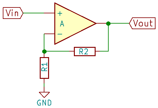
We can set gain of an op-amp by choosing appropriate resistors values. Here is a non-inverting op-amp circuit model, which I used in above schematic.
The gain of this circuit will be (R2 / R1 ) + 1.
So, we can choose appropriate resistors to set the gain. However, as far as I learned, we should not set large gain like 150 in single stage of op-amp rather we need to use multiple stages to achieve it. Final gain will be the value of multiplication of individual stage gains.
In my purpose, two stages are sufficient to get desired gain. After checking available resistors I decided to use resistors 1KΩ and 20KΩ for first stage, which will give gain 21. For second stage I used 1KΩ and 6.8KΩ, which gives gain 7.8.
Thus, overall gain of the circuit will be 21 x 7.8 = 163.8
It is near to my target gain of 168.64.
Thus input signal of 24.905 mV (for 600°C) from thermocouple will induce a 163.8 x 0.024905 = 4.07 V in microcontroller ADC input.
Stabilize Input
The circuit I built initially did not have input filtering. Thus the temperature reading was jumping frequently. Thus used RC filter built with TCR1 (1KΩ) resistor and TCC1 (100nF) capacitor as seen in schematic.
Protect From Shorting and Higher Voltage
Two zener diodes, ZD1 and ZD2 connected in back-to-back are used to protect the circuit in case thermocouple touches higher voltage wires internally within soldering iron.


Leave a Reply